
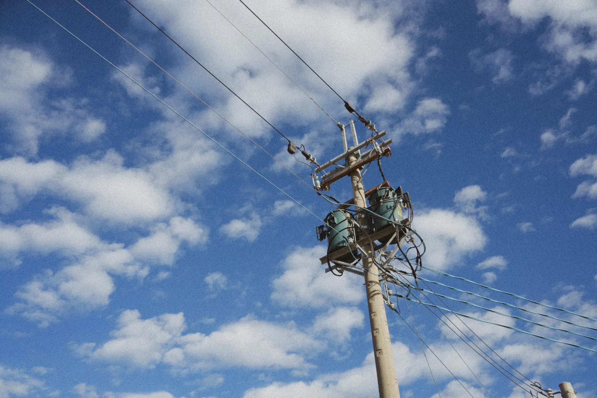
Pole-mounted transformer with wires and insulators against a blue, cloudy sky
Instrumental testing

SFRA testing on power transformers

Sweep frequency response analysis to IEC 60076-18: a non-destructive measurement that reveals the mechanical condition of the core and windings without opening the machine.

What it reveals

What it measures, and why it matters.

A power transformer can be electrically sound and mechanically compromised at the same time. A through-fault, a road transport, a seismic event, or simply twenty years of electrodynamic stress can shift the windings away from the position they were built in. Turns ratio, winding resistance and insulation resistance can all stay within limits while the internal geometry has already changed.

Frequency response is sensitive to exactly that geometry. The distributed inductances and capacitances inside the machine depend on the relative position of turns, limbs and clamping structures: if something moves, the resonances of the transfer function shift in frequency and change in amplitude. That is why SFRA sees defects that no other routine electrical test intercepts.

Comparing the signature recorded today against a reference reveals core movement, winding deformation and displacement, partial winding collapse, loosened or failed clamping structures, shorted turns and open windings. The result is not a pass or fail: it is a diagnosis with a location, because different frequency regions tell different parts of the machine's story.

  • Field measurement
  • Reference fingerprint
20 Hz1001 k10 k100 k2 MHz0-20-40-60-80-100dBDEVIATION
Comparison with the reference fingerprintComputed from a model · RLC winding network, 20 Hz to 2 MHz under IEC 60076-18
Test parameters

The numbers that define the measurement.

20 Hz to 2 MHz measurement band

The range prescribed by IEC 60076-18. Below the kilohertz range the magnetic circuit responds, in the mid range the winding-to-winding interactions, above 100 kHz the geometry of the individual winding and the test leads.
Test voltage below 10 V RMS

The standard keeps the injected signal below 10 V RMS precisely to avoid altering the magnetic state of the machine: the test is repeatable and leaves no trace on the core.

Non-destructive, machine off

Carried out out of service, with the transformer isolated and earthed. No high-voltage stress, no risk to the insulation: SFRA can precede and follow any other test without affecting its outcome.

Three comparisons, not one

The trace is read against the historical signature of the same machine, against the other two phases of the same transformer, and against a sister unit of identical construction. Where no history exists, the other two comparisons remain available.

Test leads as prescribed by the standard

Double-shielded coaxial cables and flat, wide earthing braids. Above 100 kHz the leads become part of the measurement: an improvised connection produces a deviation that looks like a defect but isn't.

Report with traces and diagnosis

We deliver the traces for every winding in an open format, the comparison against the available references, the interpretation by frequency region, and whether the machine can be returned to service.

How it works

From lock-out/tag-out to the report.

  1. Site survey and lock-out/tag-out

    Isolating, earthing and discharging the transformer, opening the line and neutral connections, verifying the absence of voltage. We record the machine's actual configuration: the next campaign has to reproduce it identically.

  2. Frequency response measurement

    Injecting a low-voltage sinusoidal signal and recording the response across the whole spectrum, with double-shielded coaxial cables and flat earthing braids as prescribed by IEC 60076-18. Repeated on every winding and in every configuration required.

  3. Comparison against the reference signature

    Overlaying the machine's historical trace, the other phases, and a sister unit. Deviations are read by frequency region, because the region tells whether the suspicion is on the core, the winding or the clamping.

  4. Report and archived signature

    A report with traces, comparisons and diagnosis, plus archiving of the signature and test conditions: without those, the next campaign can't be compared against this one.

Reference standard

IEC 60076-18

Power transformers – Part 18: Measurement of frequency response

Introduced in 2012, it defines how a transformer's frequency response is measured and documented. It sets the measurement range from 20 Hz to 2 MHz, keeps the test voltage below 10 V RMS to avoid altering the machine's magnetic state, and prescribes double-shielded coaxial cables earthed with flat, wide braids. Repeatability is the point: the standard requires recording the test conditions so that today's measurement is comparable with the one taken five years from now.

Instrumentation
Frequency response analyser
Measurement
Double-shielded coaxial cables
Signal
Flat, wide earthing braids
Earthing
Test setup
Measurement range
20 Hz to 2 MHz
Injected signal
Sinusoidal, < 10 V RMS
Machine status
Out of service, earthed
Repetition
Every winding, every phase
Traces
Open format, archived
In the field

Banzi–Montemilone electrical substation

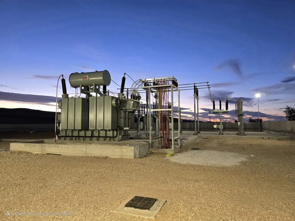
On the transformer at the 150/20 kV Banzi–Montemilone substation (PZ) we carried out a frequency response analysis, comparing the recorded traces against the machine's reference values. The comparison showed no significant deviations: mechanical integrity confirmed and the transformer fit for service.

See our completed projects
150/20 kV electrical substation between Banzi and Montemilone, overall view
Frequently asked questions

What clients ask us before they call.

If your question is not here, call us: a technician answers, not a switchboard.

Call us: +39 0881 377590
What exactly does the SFRA test measure?

It measures a winding's transfer function: a low-voltage sinusoidal signal is injected and the response is recorded as frequency varies, from 20 Hz to 2 MHz. The resulting curve depends on the inductances and capacitances distributed inside the machine, in other words on its internal geometry.

Do you need a previous reference signature?

It's the best condition, but not the only one. Without a history, the three phases of the same transformer are compared against each other, and the machine against a sister unit of identical construction. The first campaign, in any case, also serves as the starting signature for every one that follows.

Does the transformer need to be out of service?

Yes. The test is carried out with the machine isolated, earthed and with the line connections open. It is not, however, a destructive test or a stress test: the injected voltage stays below 10 V RMS and leaves no effect on the machine.

What defects can it detect?

Core movement, winding deformation and displacement, partial winding collapse, loosened or failed clamping structures, shorted turns and open windings. These are mechanical defects that routine electrical tests may not see at all.

When is it worth carrying out?

After a through-fault or a protection trip, after transport or lifting, after a seismic event, before and after a workshop repair, and as a reference measurement when a new machine is commissioned.

Why do the test leads matter so much?

Because above 100 kHz the cables and earth connections become part of the measurement. IEC 60076-18 prescribes double-shielded coaxial cables and flat, wide earthing braids, and requires the test to be repeated with the same leads: otherwise you're comparing two measurements that differ because of how they were taken, not because of the machine's condition.

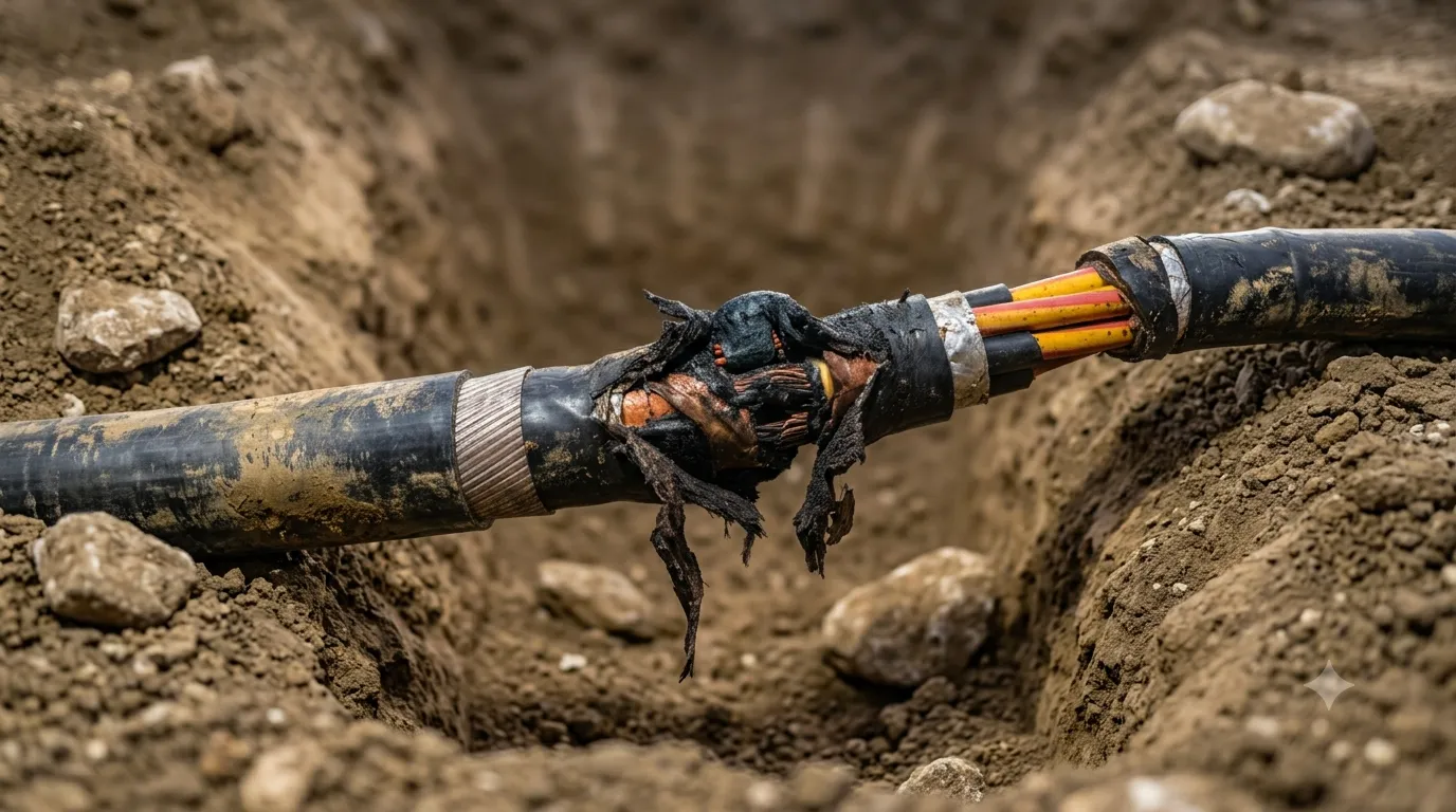
Giunto di un cavo di media tensione bruciato e scoperto in uno scavo, con i conduttori in rame esposti

A fault does not wait. Neither do we.

Talk directly to the people who put their hands on the plant. No forms, no waiting: one call and we are on it.